|
|
|
|
“The data forming the basis on this report has been collected through
the joint effort of Acona AS.
Acona
has gathered the data to the best of our knowledge, ability, and in good faith
from sources to be reliable and accurate.
Acona
has attemted to ensure the accuracy of the data, though, Acona makes no
representations or warraties as to the accuracy or completeness of the reported
information.
Acona
assumes no liability or responsibility for any errors or omissions in the
information or for any loss or damage resulting from the use of any information
contained within this report.
This
document may set requirements supplemental to applicable laws. However, nothing
herein is intended to replace, amend, supersede or otherwise depart from any
applicable law relating to the subject matter of this document.
In
the event of any conflict or contradiction between the provision of this
document and applicable law as to the implementation and governance of this
document, the provision of applicable law shall prevail.”
Revision and Approval Form
|
Technical report |
|
Title |
|
ACES User Manual |
|
Revision History |
Date |
Prepared |
Approved |
|
|
1.0 |
01.10.2014 |
Acona |
Acona |
|
Name |
Date |
Signature |
|
Prepared by |
|
|
|
Acona |
01.10.2014 |
|
Table of Contents
2.1 Types of field development
3.2 Well maintenance/intervention
5 UFR – Umbilical, flowline, riser
5.2 Diameter and thickness of pipelines
8 Tie-back projects with topside
modifications
8.2 Input definition for topside modification in tie-back
projects
9 Allowances and contingencies
12 Units and conversion factors
Figures
Figure 1 - Illustration of
overall structure
Figure 3 - Rig categories
and classes of intervention
Figure 4 -Subsea
production stations – examples.
Figure 5 - Definition of
terminology
Figure 6 - Riser concepts
- illustrations
Figure 7 -
Flowline/pipeline groups - examples
Figure 8 - Illustration of
direct electric heating
Figure 9 - Illustration of
pipe-in-pipe
Figure 10 - Illustration
of platform concepts
Figure 11 - Functionality
of platform concepts
Figure 12 - Platform main
functional areas
Figure 13 - Inlet system A
and B
Figure 14 - Illustration
of the full processing case with two inlet systems
Figure 15 - Illustration
of tie-back projects
Figure 16 - Illustration
of space/area challenges in modification projects
Figure 17 - Tie-in of
wells, flowlines/risers and export pipelines to platform topsides
Figure 18 - Illustration
of modification weight definition
Figure 19 - Pre-fabricated
manifold assembly for a tie-back project
Figure 20 - Allowances and
contingencies
|
DEH |
Direct electric heating |
ESP |
Electric submersible pump |
|
EUR |
Euro |
FPSO |
Floating production, storage and offloading unit |
|
MODU |
Mobile offshore drilling unit |
MSL |
Mean sea level |
|
NOK |
Norwegian kroner |
NPV |
Net present value |
|
PLEM |
Pipeline end manifold |
PLET |
Pipeline end terminal |
|
Sm3 |
Standard cubic meter |
Sm3 oe |
Standard cubic meter oil equivalent |
|
TLP |
Tension leg platform |
TVD |
Total vertical depth |
|
USD |
U.S. dollar |
|
|
There
are two options for how to use the program; the PROSPECT version and the
ENGINEERING version
The
data basis and the calculation methods are the same for the two versions. But
the input to the analyses is quite different.
Option 1 – Prospect analyses
For prospect analyses the
available design basis information is very preliminary, limited and immature.
Only a few input parameters are
required. Additional design basis assumptions are generated automatically based
on assumptions.
Option 2 – Engineering;
feasibility and concept studies
For feasibility and concept
studies the design basis is more mature, and technical parameters may be
available from other studies. A more detailed
list of input parameters will be required.
The descriptions in the
following sections relate to the Engineering version
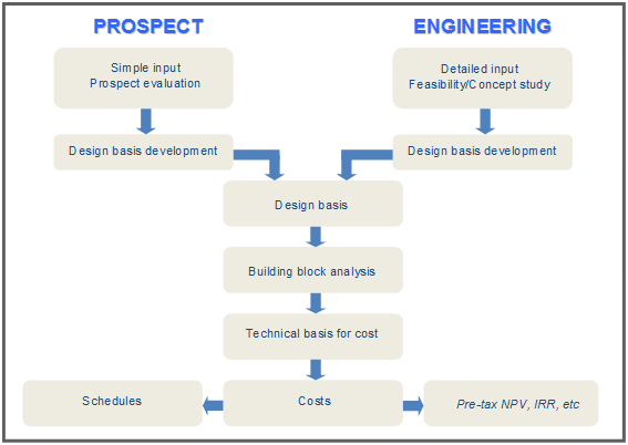
Figure 1 - Illustration of overall
structure
The following general input is
required:
·
Name of project
·
Cost reference year. All costs
(USD, NOK or USD) are real costs
related to this year.
·
Water depth for the field
(normally the at platform location)
·
Location of field (four
different alternatives)
·
Type of project, see below. A stand-alone project always includes a
new platform. A tie-back project
includes some platform modifications
·
Initial reservoir pressure
(bar)
For specific cash flow analyses
it is necessary also to specify:
·
Number of stream days per year
·
Discount rate for NPV
calculations
·
Recoverable volumes for
oil/condensate and gas given in specified units
·
Price and tariff or
oil/condensate and gas given in specified units
In the illustration below it is
distinguished between four types of field development.
Mobile production systems and
permanent stand-alone developments are both stand-alone
projects. Mobile systems are suitable for small fields with short field
life.
Satellite developments are tie-back projects suitable for small to
medium size fields not too far away from existing infrastructure.
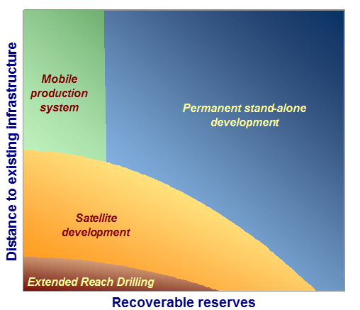
Extended reach drilling can be
used in special cases where new hydrocarbons are found within drilling reach
from existing infrastructure with drilling facilities.
Up to 10 well groups can be defined. All wells in one group are identical. For
a specific case with several wells it is possible to define only one well
group. The well group will then represent an “average” well or “typical” well.
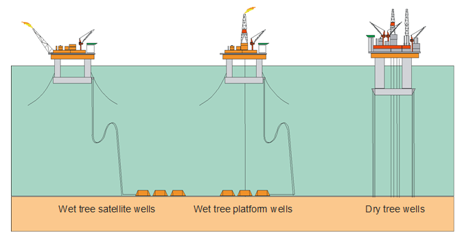
Figure 2 - Types of wells
The well function must be defined. There are three alternatives:
Producer, water injector and gas injector.
The well type must be defined. There are three alternatives: Dry tree
well, wet tree platform well and wet tree satellite well. A dry tree well and a
wet tree platform well is located underneath the platform, while a wet tree
satellite well is located some distance from the platform.
The drilling method must be defined. There are three alternatives:
Platform rig, jack-up MODU and semisubmersible MODU.
The true vertical depth (TVD) must be defined. This is the vertical
distance from mean sea level (MSL) to the bottom of the well.
The horizontal reach must be defined. This is the horizontal distance
between the wellhead the bottom of the well.
The horizontal section must be defined. This is the length of the
horizontal section the well.
The wells can have artificial lift. Gas lift or ESPs can be
selected.
The average progress rate for drilling (m/day) must
be defined.
The completion time must be defined. This is the number of days needed
for completion of the well.
It is distinguished between
three classes of intervention: A light, B
medium, C heavy. For each class of intervention it is necessary to define frequency and duration.
The frequency is the number of interventions per well per year.
The duration is the number of days needed for each intervention.
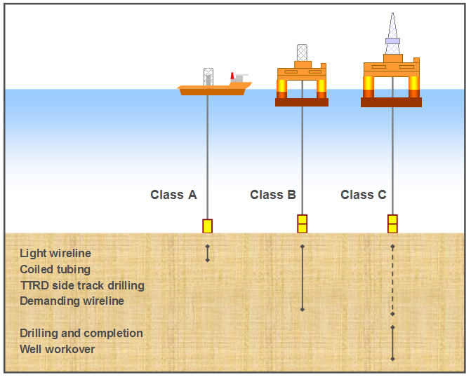
Figure 3 - Rig categories and classes of intervention
Up to 10 different production
stations can be defined. Each production station comprises one or more wells.
·
The number of X-mas trees must be defined.
·
The number of template well slots must be defined. The number of slots
may be higher than the number of X-mas trees.
·
The number of single well slots must be defined. A single well may be
connected to a template/manifold or directly to the production platform.
·
It has to be specified whether
template wells and single wells will have a protection structure or not.
·
The pressure class for the X-mas trees must be defined. There are three
alternatives: 5000 psi, 10000 psi and 15000 psi.
·
The number of multiphase flow meters associated with
each production station must be defined.
·
The number of multiphase pumps associated with each
production station must be defined.
·
The distance between the production station and the platform must be
defined.
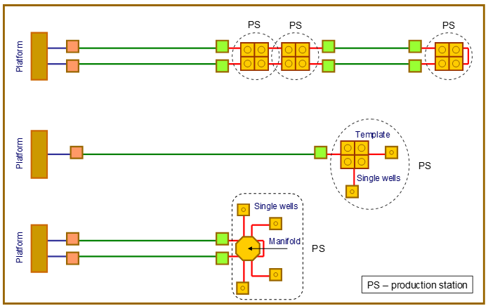
Figure 4 -Subsea production stations – examples
Up to 10 different groups of
flowlines and risers can be defined. Each group can comprise several pipeline
segments, spools and risers.
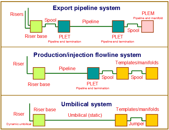
Figure 5 - Definition of terminology
The function of each group must be defined. There are five options: Oil
export, gas export, water injection, gas injection, wellstream production. A gas lift line can be considered as a gas
injection line.
The type of material must be defined. There are four
options: Carbon steel, clad steel, Cr steel, flexible pipe.
The surface protection must be
defined. There are five options: No protection or cover, coating, insulation,
insulation with direct electric heating (DEH) and pipe-in-pipe.
The installation/lay method must be defined. There are three options:
S-lay, J-lay and reeling.
The amount of gravel dumping must be defined. There
are four options: no gravel dumping, little, medium and high degree of gravel
dumping.
The type of risers must be defined. There are four
options: J-tube, supported steel riser, tensioned steel riser, flexible riser.
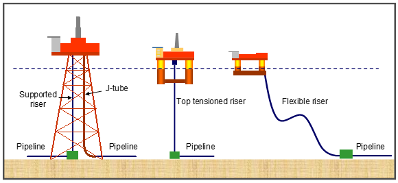
Figure 6 - Riser concepts - illustrations
J-tubes and supported risers
are only used with fixed platforms. J-tubes are used for smaller diameters of
flowlines (<16”) while supported risers can be used for large diameters.
Top-tensioned risers are used
with tension leg platforms, spars and jack-ups.
Flexible risers can be used
with all types of platforms.
The total length of pipeline per group must be defined. There may be
several pipe segments in the group, but they all have the same characteristics.
The number of pipe segments per group must be defined.
The number of spools per group must be defined. A
spool is a relatively short pre-fabricated pipe element that accommodates
thermal expansions and is used for connecting different parts of the system.
The number of pipeline end terminations (PLETs) per
group must be defined.
The number of pipeline end manifolds (PLEMs) per group
must be defined.
The number of risers per group must be defined.
(The number of riser bases is
determined automatically).
It has to be specified whether
HIPPS (high integrity pressure protection system) is used, or not.
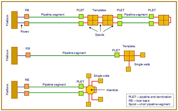
Figure 7 - Flowline/pipeline groups - examples
Diameter
and thickness for each pipeline group can be
given as input.
Diameter and thickness is also
be proposed by the program. In that case the following input must be given:
·
Flow capacity
·
Inlet pressure
·
Pressure drop in pipeline
The flow capacity (Sm3
oe/day) can for this purpose be given
as:
F
= Oil + 1000 Gas + W
Where Oil is the oil flow in Sm3/d, Gas is the gas flow in mill.Sm3/d and Water is the water flow in m3/d.
If the proposed values are to
be used, the selected values must be put equal to the proposed values.
Length
and number of segments for umbilicals and
electric power cables must be defined.
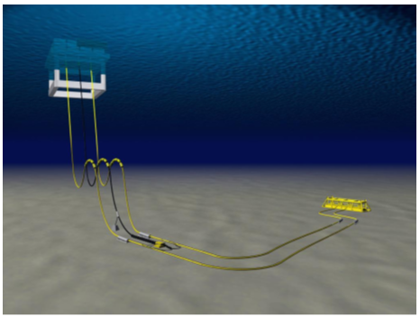
Figure 8 - Illustration of direct electric heating
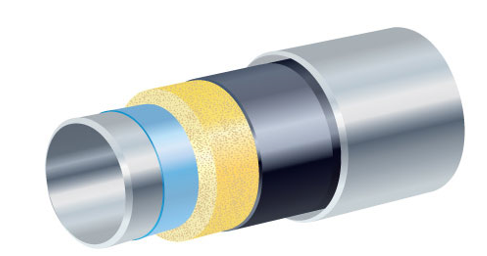
Figure 9 - Illustration of pipe-in-pipe
The type of platform substructure must be defined. There are five
alternatives:
·
Fixed steel platform (jacket)
·
Tension leg platform (TLP)
·
Spar platform
·
Semisubmersible platform (Semi)
·
Buoy
·
Production ship (FPSO, floating
production, storage and offloading unit)
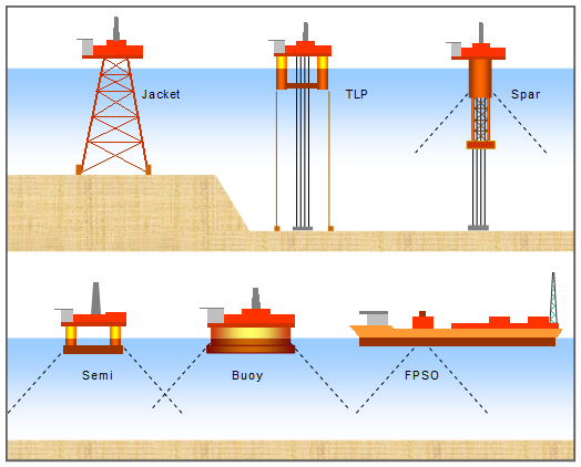
Figure 10 - Illustration of platform concepts
The dimensions and weight of
the substructure will be determined on the basis of topside weight and oil storage
volume. A typical oil storage volume is 150000m3. (For Spar
platforms only smaller volumes should be considered).
·
Integrated
oil storage can only be specified for Spars, Buoys and FPSOs! Fixed platform,
TLP and semi will have to use a leased storage tanker.
·
Dry
tree wells can only be specified for Jackets and TLPs!
·
Drilling
rig can not be used on FPSOs!
·
A Jacket is attached to the sea
bottom by piles.
·
A TLP is attached to the sea
bottom by tension legs (tethers) and piles.
·
Spars, Semis, Buoys and FPSOs
are anchored by means of a chain-wire-chain system and suction anchors.
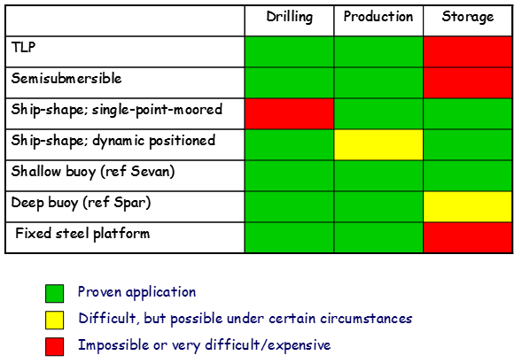
Figure 11 - Functionality of platform concepts
The main elements of a platform
are shown in the illustration below. There are five main functional areas:
·
Living quarters with helideck
·
Utility area, including power
generation and water injection facilities
·
Drilling area, including
derrick and mud systems
·
Wellhead area
·
Process area
Other significant pieces of
equipment are flare tower, deck cranes and life boat stations. In some cases
there are special support structures for modules and heavy equipment packages.
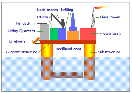
Figure 12 - Platform main functional areas
The number of beds must be defined.
This is the basis for weight estimation.
It has to be specified whether
a drilling package is to be included
or not.
The maximum well length must be defined. The weight of the drilling
package is scaled on the basis of maximum well length.
The platform can have one or
two inlet systems, see illustration below. System B has higher pressure than
system A (or equal).
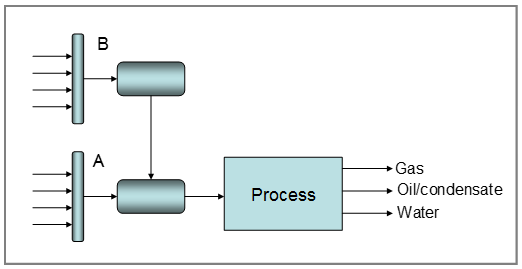
Figure 13 - Inlet system A and B
For each of the two systems the
following input parameters have to be defined:
·
The oil production rate (capacity) must be defined.
·
The gas production rate (capacity) must be defined.
·
The inlet separator pressure must be defined.
·
The up-stream shut-in pressure must be defined.
·
The number of dry tree well slots must be defined.
·
The number of riser slots must be defined (riser slots related to
oil/gas export are not to be included in this number).
(Guidance: suggested values for
the up-stream pressure are shown)
If there is only one inlet
system, no data are to be given for system B.
The process concept case must be defined. There are five alternatives:
·
Concept 1: full processing of
oil/gas/water, see illustration below
·
Concept 2: simplified process;
one-stage separation only
·
Concept 3: simplified process;
one-stage separation with water removal; oil and gas export in common pipeline
·
Concept 4: no processing;
wellstream export
·
Concept 5: Tie-back project.
The host platform is assumed to be a full processing platform with one inlet
system. If the tie-back project needs a separate in-let system, two in-let
systems must be specified. Existing systems are up-graded/modified.
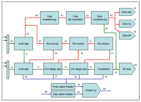
Figure 14 - Illustration of the full processing case with two inlet systems
The following parameters have
to be defined:
·
Maximum liquid capacity; the
maximum combination of oil/condensate and water. Guidance: (oil3/2 +
water3/2)2/3 where oil
is the maximum oil production and water
is the maximum water production
·
Produced water treatment
capacity. Guidance: about 75 percent of the oil production capacity
·
Water injection capacity.
Guidance: about 150 percent of the oil production capacity
·
Gas export capacity.
·
Gas injection capacity
·
Gas lift capacity
·
Oil/condensate density (API
gravity)
·
Oil/condensate stabilization
(stable oil/condensate for tanker transport)
Design
pressure (Guidance: suggested values are
shown)
·
Oil/condensate export pressure
·
Gas export pressure
·
Gas injection pressure
·
Gas lift pressure
·
Water injection pressure
Export
riser slots
·
Number of oil export riser
slots
·
Number of gas export riser
slots
Power
generation
·
Alternative 1: main power
generation and emergency power generation on platform
·
Alternative 2: main power
import via cable; emergency power generation on platform
Note: Gas export compressors
are always assumed to be powered by gas turbines!
Systems
that may or may not be included
·
Test separator
·
MEG regeneration system
(relevant for long tie-backs)
·
De-sulphatation of injection
water
·
Gas sweetening (removal of CO2
and/or H2S)
·
Gas conditioning (NGL
extraction)
·
Gas de-hydration (water
dew-point control)
·
Fiscal metering of
oil/condensate
·
Fiscal metering of gas
A tie-back concept is field
development concept with certain characteristics:
·
There are no manned facilities
on the field – only a subsea well system or an unmanned wellhead platform
·
The well-stream is transferred
to an existing platform – host platform
·
The host platform may supply
water and/or gas for injection
·
The host platform may be a fixed
platform or a floating platform
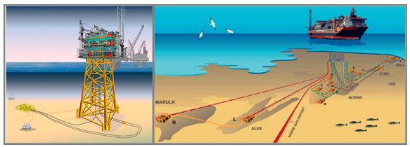
Figure 15 - Illustration of tie-back projects
There are several requirements
to a host platform:
·
The host platform must have
sufficient remaining service life
·
The host platforms must have
possibilities for tie-in of flowlines and umbilicals via existing or new
risers or J-tubes
·
Well control systems
must be installed on the host platform
·
An acceptable tie-in solution
may require a new inlet separator and metering system integrated with
the existing systems
·
The host platform must have sufficient
capacity in all main platform systems (process/utilities)
·
De-bottlenecking
can to some degree enhance the throughput
·
Installation of parallel
trains is normally not an option due to costs, and lack of space and weight
carrying capacity
·
Production and injection
profiles for the tie-back project are normally defined to match the
available capacities on the host platform. Timing of the tie-back project
is therefore essential
Installation of new equipment
may be limited by lack of space and weight carrying capacity. Verification of
the feasibility of potential modifications can be very complex, even for small
modifications
Cost estimates have a wider
range of uncertainty than estimates for new platforms. Use of 3D CAD models may
be required even for feasibility studies.
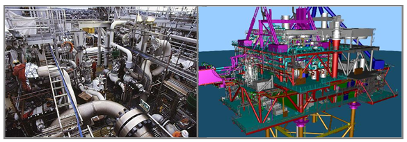
Figure 16 - Illustration of space/area challenges in modification projects
New equipment associated with a
tie-back project may include:
·
risers, pull-in and pigging
equipment, see illustration below
·
inlet separator
·
re-compression equipment (only
if the new in-let separator has a higher operating pressure than the existing inlet
separator)
·
metering system related to the
new inlet system
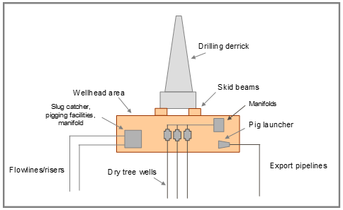
Figure 17 - Tie-in of wells, flowlines/risers and export pipelines to platform
topsides
The topside modification
weights are based on differentials between two platforms; platform 1 and
platform 2.
Platform 1 is the modified host
platform, and platform 2 is the host platform before the modification, see
illustration below.
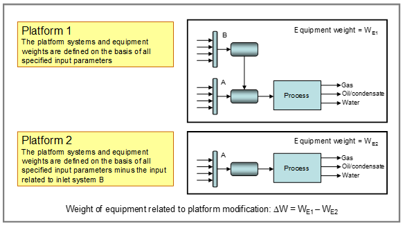
Figure 18 - Illustration of modification weight definition
This means that the platform
input must be given in such a way that the capacities reflect the design of the
modified host platform.
The process concept must be set
equal to: Process modification (…)
Inlet system B is dedicated to
the tie-back project. The input
related to system B must define the oil and gas volumes, the pressures, and the
number of slots needed.
There
are two options for inlet system B:
1)
Minimum modification: Direct tie-in to existing
inlet separator (select 1 inlet separator)
2)
Medium modification: Install a new inlet separator
and metering system with necessary adjustments to other systems (select 2 inlet
separators)
There can be cases where larger
modifications are required. This can be related to the age and functionality of
the host platform. In such cases it is recommended to carry out a specific
technical study including 3D CAD modelling of relevant areas of the platform.
Weights can then are given as direct input for cost estimation.
Base case should be to select
modification weights equal to the proposed weights.
New equipment and structures
may in principle be pre-fabrication onshore and installed offshore, or built
piece by piece offshore. The degree of pre-fabrication (rough estimate) must be
defined.
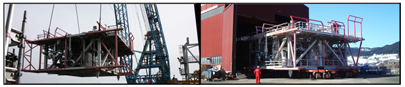
Figure 19 - Pre-fabricated manifold assembly for a tie-back project
The following definitions are
used:
Base
estimate is the sum of the identified
quantities and costs and an allowance.
The
allowance is a quantity to be included
in the weight estimates (basis for cost) to account for inaccuracies and
incompleteness in the definition of equipment, components and materials.
The
expected cost is the sum of the base
estimate and a contingency. The expected cost is the basis for economic
evaluations.
Contingency
is a correction to compensate for the effects of skewed (non-symmetric)
distributions for each of the components in the estimate and to cover for
unspecified cost elements.
Contingency
shall cover for uncertainty within the given scope, which may lead to different
design* (design changes, design development, different execution method or
different timing).
Reserve:
If significant uncertainties in the project scope and frame conditions remain
at project sanction, the management or joint venture may decide to include a
project reserve.
*The
reason for a design change is most often that the original solution was
found unacceptable and substituted by a different and more expensive
solution. Therefore design changes cause cost increases rather than decreases!
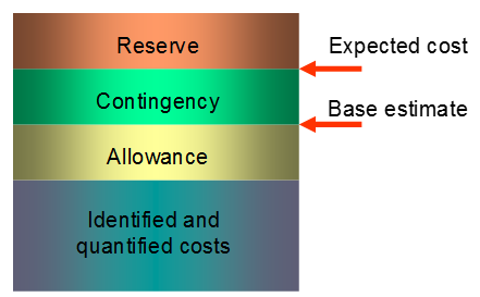
Figure 20 - Allowances and contingencies
Removal costs are calculated on
the basis of estimated quantities for the field development system that is
defined in the program. No special input is required.
The physical elements to be
removed or secured are included in the following groups:
·
Wells (plugging and
abandonment)
·
Platform topsides
·
Platform substructure
·
Mooring lines, anchors, piles
·
Risers, conductors
·
Flowlines, umbilicals and
cables
·
Export pipelines
·
Subsea equipment and structures
·
Sea bottom clean-up
For each group the following
cost categories are considered:
·
Management of the removal
project
·
Engineering
·
De-commissioning
·
Removal operation including
transportation to shore
·
Dismantling and re-circulation
or disposal of materials
·
Contingency
Calculation of NPV and other
economic indicators are performed based on the general input and data
generated in the program.
For the Cost Engineering Module, Production profiles must be defined. Data
is entered year by year. The annual production can be estimated by:
Daily
Production x Production days per year
The number of production days/
year is defined by Stream days or Calendar days.
Oil production is set in Mill.Scm3.
Gas production is set in Bill.Scm3.
For the Prospect Evaluation Module, there are two options for production
profiles input: Alternative 1 and Alternative 2.
By choosing Alternative 1, the
program estimates a general production profile based on the input information
provided. Basis for calculation are the Recoverable volumes of Oil and Gas
specified, and the average stream days per year. The program will suggest two
values based on internal calculations:
·
Percentage of annual production
at plateau relative to total production
·
Percentage of accumulated
production at end of plateau.
These two parameters will
define the generic production profile. Please note that these values can always
be overwritten.
By selecting Alternative 2, the
process is similar to the Cost Engineering Module, where the annual production
for Oil and Gas must be defined as input.
There are two other parameters
to define in the Economy tab.
·
Include / exclude Removal costs
in NPV analysis
·
Lease / purchase of floating
production units
Currency:
NOK per USD = 6,00
NOK per EUR = 8,00
Volume:
1 barrel oil ≈ 159 litre
1 scm oil ≈ 6.29 barrels
1 tonne oil ≈ 1.18 scm oil
1 scm oil ≈ 0.85 tonne oil
1 scm gas = 35.315 scf gas
1000 scm gas = 1
scm o.e.
1 scm NGL = 1 scm
o.e
1 scm condensate
= 1 scm o.e.
Length:
1 ft = 0.3048 m
1 m = 3.2809 ft
1 in = 2.54 cm
1 km = 0.62137 miles
Numerical:
1 mill (M) = 1 million = 1x10⁶
1 bill (G) = 1 billion = 1x10⁹
Pressure:
1 bar = 14.5038
psi
1 psi = 0.0689
bar